
Quantum Programming with High School Math: Part 3
Recap on Previous Articles
This article is part of a series. The earlier articles are
Syllabus Overview
In the earlier articles, I limited to using real numbers to demonstrate interactions between a quantum gate and a qubit. You may have noticed that this resulted in the rotation of the quantum state vector within only the x-z plane in the Bloch sphere.
This quantum state behavior does not seem to present any obvious advantage over the classical bit system as the measurement of the qubit will collapse the quantum state back to one of the two logical values.
The true power of the qubit, unbeknownst to many, lies in the ability to encode information in one additional dimension not found in the classical bit. This 3rd dimension is known as the relative phase of a qubit, which is analogous to the phase difference between two waves giving rise to interference effects in classical physics.
In this context, the relative phase between the two wave functions for |0⟩ and |1⟩ allows the qubit to exhibit interference effects in a superposition state. This quantum interference is precisely the "quantum advantage" that enables a quantum program to bias the probabilities towards producing the desired output.
In this article, I will use complex numbers to provide a more complete description of the qubit in mathematics. I will also introduce single-qubit quantum gates with operations that manipulate the relative phase.
Representing Physical Attributes in the Coefficients
Recall, in Part 1, we learnt that the quantum state of a qubit |Ψ⟩ can be described as a linear combination of two complex numbers α and β.
However, in Part 2, we learnt that the quantum state of a qubit has three physical attributes: amplitude in |0⟩, amplitude in |1⟩, and relative phase between |0⟩ and |1⟩. So, how do we capture these three physical attributes in two complex coefficients?
General Equation of Quantum State of a Qubit
To encode the three physical attributes in α and β, we expand the complex coefficients to a more general form, where α and β. In doing so, we can rewrite the linear equation of a quantum state into the general form below.
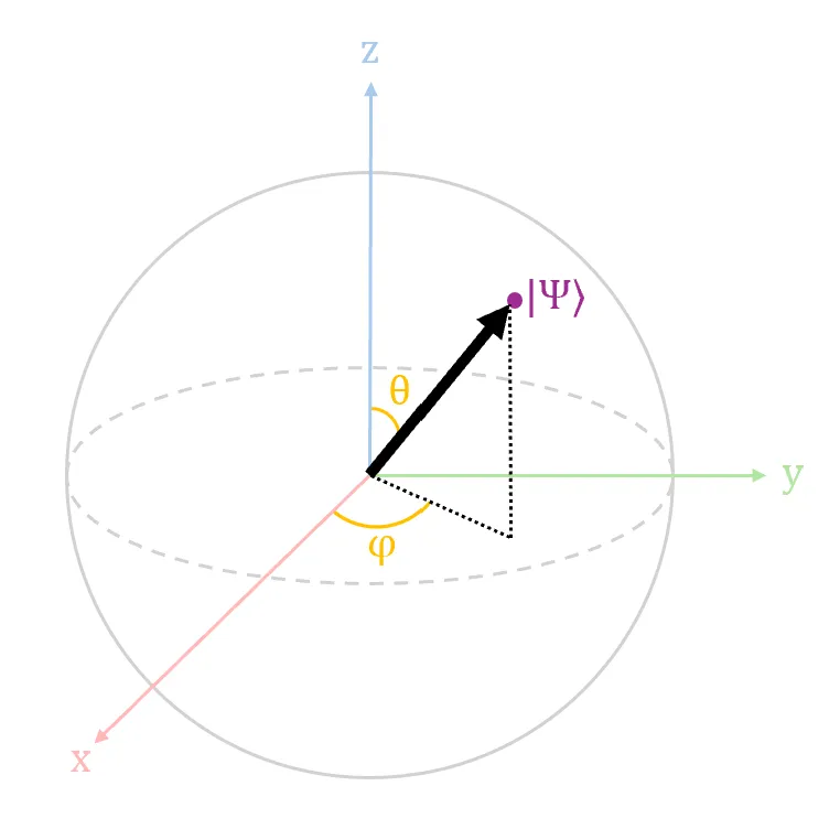
With the quantum state in this general form, it becomes easier to be mapped into the Bloch sphere, as shown in Diagram 1 above. Intuitively, the amplitude in |0⟩ is captured in , the amplitude in |1⟩ is captured in , and the relative phase is captured in .
Math for Relative Phase
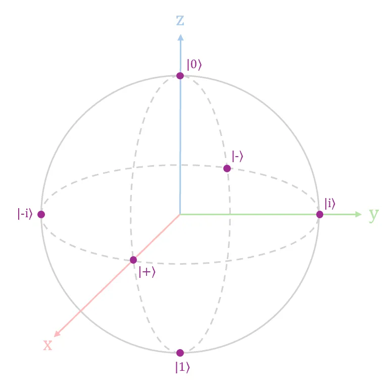
Given an initial state vector at |+⟩, when we rotate it around the z-axis for values of radians, the values for respectively (mathematically, these values are computed using Euler's identity). This coincides with the popular labels |+⟩, |i⟩, |-⟩ and |-i⟩ as shown in Diagram 2 above along the equator of the Bloch sphere. This quantum operation of rotating a state vector around z-axis is known as a phase shift.
The Inconsequential Global Phase
At this juncture, you might realize that there is an inconsistency between the expanded terms of α and β. β has two terms containing both angles θ and φ, whereas α only has one term containing the angle θ. This is because the general equation for quantum state shown earlier already has the global phase factored out, leaving behind the relative phase in the equation.
Recall from earlier that the relative phase is analogous to the phase shift difference between two waves. In the same nature, the global phase is analogous to the absolute phase shift of both waves. However, the global phase is widely regarded as having no effect on the measurement results of a quantum state, and thus discarded by default from the general equation.
If you are interested in the math on how to factor out the global phase, do check out the numerous online material covering this topic using search keywords "quantum phase factor". I decided not to include the math for this topic here to keep the article short for easy reading.
Quantum Gates with Complex Parameters
In the following sections, I will introduce fundamental single-qubit quantum gates that affect the relative phase of the qubit.
Math for Pauli-Z (Z) Gate
The Z gate takes in one qubit input, flips the input relative phase from +1 to -1, and vice versa from -1 to +1. Due to this phase-flip operation, the Z gate is also known as a "phase-flip operator" or "phase shift by φ = π". In the Bloch sphere, the Z gate performs a rotation on the quantum state vector by π radians around the z-axis.
The matrix for the Z gate is defined as
The effect of the Z gate is shown below in both Dirac and vector notations.
Math for Pauli-Y (Y) Gate
The Y gate takes in one qubit input, performs a combination of a bit-flip (e.g., X gate) and a phase-flip (e.g., Z gate), specifically Y = iXZ.
The matrix for the Y gate is defined as
The effect of the Y gate is shown below in both Dirac and vector notations.
Math for S Gate
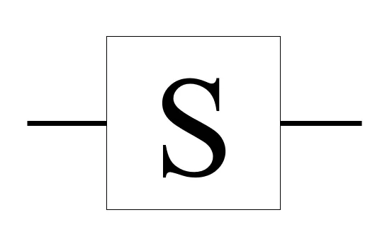
The S gate takes in one qubit input and shifts the input relative phase by radians. Due to this phase-shift operation, the S gate is also known as a "phase (S) gate" or "phase shift by ". In the Bloch sphere, the S gate performs a rotation on the quantum state vector by radians around the z-axis.
Fun fact: the S gate has been historically observed to be occasionally called the P gate to refer to the same the phase shift by operation.
The matrix for the S gate is defined as
The effect of the S gate is shown below in both Dirac and vector notations.
Math for T Gate
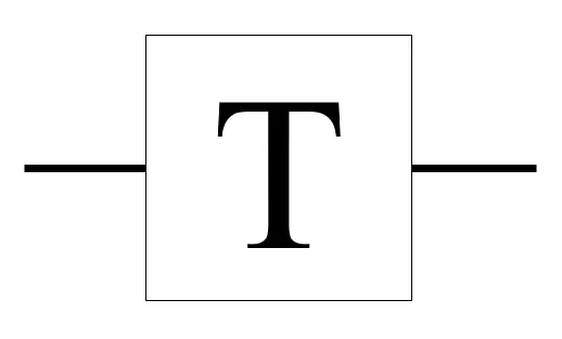
The T gate takes in one qubit input and shifts the input relative phase by radians. Due to this phase-shift operation, the T gate is also known as a "phase (T) gate" or "phase shift by ". In the Bloch sphere, the T gate performs a rotation on the quantum state vector by radians around the z-axis.
The matrix for the T gate is defined as
The effect of the T gate is shown below in both Dirac and vector notations.
Review
In this article, we learnt how to represent the 3 physical attributes in the general equation of quantum state of a qubit. The 3 physical attributes are amplitude in |0⟩, amplitude in |1⟩, and relative phase between |0⟩ and |1⟩. We also learnt of fundamental quantum gates that operate on the relative phase of a qubit.
Bonus Question
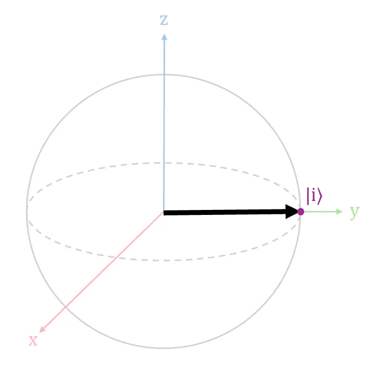
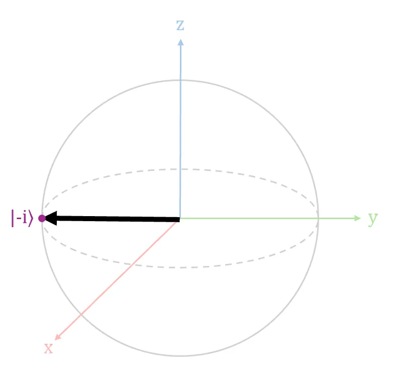
Given that an input qubit is in either the |i⟩ state (shown in Diagram 7 above) or in the |-i⟩ state (shown in Diagram 8 above), design a circuit that allows you to determine upon measurement which of the two states the input qubit is in. (Hint: You can begin the QuICScript code with "H,P," or "X,H,P," to initialize input qubit to |i⟩ or |-i⟩ respectively. You can use Quantum-in-a-Browser to check against your answer. Note that QuICScript uses P to refer to the phase shift by π/2 operation.)
See Answer
When a measurement is applied directly to the |i⟩ or |-i⟩ state, one will have a 50% chance to observe either a |0⟩ or |1⟩. To the observer, this direct measurement approach is unable to provide information on whether the input qubit is in a |i⟩ or |-i⟩ state.
One approach to overcome this challenge is to first shift the phase of the qubit by (with one S gate) to a |-⟩ or |+⟩, followed by a rotation about the y-axis (with one H gate) to a |1⟩ or |0⟩. In this manner, observing a |0⟩ upon measurement means that the input qubit was in |-i⟩; observing a |1⟩ upon measurement means that the input qubit was in |i⟩.
If input qubit is in |i⟩ state, the solution in QuICScript code is "H,P,P,H" for 1 qubit. You should observe 100% |1⟩ state.
If input qubit is in |-i⟩ state, the solution in QuICScript code is "X,H,P,P,H" for 1 qubit. You should observe 100% |0⟩ state.
Author
Nicholas Ho
Nicholas seriously enjoys learning new knowledge. He is so serious about it that his hobby is to collect hobbies. His most enduring hobby, since 1997, is to continuously explore the ever-evolving domains of applied cryptography, software development, and cybersecurity. His latest aspiration is to add the word quantum in front of each of these 3 domains. Nicholas is currently a Senior Cryptographic Engineer at pQCee.com. Akin to many Singaporeans, he also enjoys collecting popular certifications, including a CS degree, an Infocomm Security masters, CISSP, and CISA.