Quantum Programming with High School Math: Part 2
Recap on Previous Article(s)
This article is part of a series. The earlier article is Demystify Quantum Programming with High School Math Series: Part 1 - The Qubit.
Syllabus Overview
In this article, I will introduce the Bloch sphere, which provides an intuitive visual representation of the quantum state of a qubit. This visual representation also makes it easier to appreciate how a quantum gate operation transforms the qubit state.
Although complex numbers are used in quantum mechanics (QM) linear algebra, I will limit to using real numbers in this article. As such, we will cover some gates that operate only on one qubit (also known as single-qubit gates), namely Identity (I) gate, Pauli-X (X) gate, and Hadamard (H) gate.
Bloch Sphere, A First Visit
The Bloch sphere, invented by physicist Felix Bloch, is a visual presentation of the mathematical representation of the quantum state of a quit. In technical terms, the Bloch sphere is a geometric representation of a two-level quantum mechanical system aka a qubit.
Northern and Southern Hemispheres
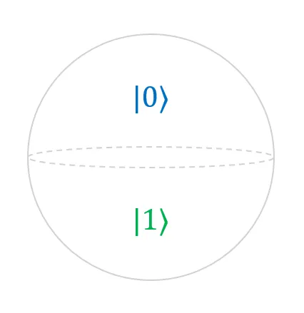
Recall, in Part 1, that the quantum state of the qubit |Ψ⟩ can be described as a linear combination of two complex numbers α and β, where α describes the amplitude that the qubit is in the |0⟩ state and β describes the amplitude that the qubit is in the |1⟩ state.
In Diagram 1 above, the northern hemisphere is the graphical representation of α; the southern hemisphere is the graphical representation of β. Together, both hemispheres form the Bloch sphere, which graphically represents the linear combination of α and β of one qubit.
The Three Axes
Here is a quick refresher on complex numbers. A complex number consists of two parts: a real number component and an imaginary number component. Specifically, a complex number, z = a + bi, where a & b are real numbers and i is the square root of -1 . Intuitively, this implies that there are four real numbers to describe a quantum state in a qubit.
However, in the context of quantum mechanics, the quantum state of a qubit can be described using only three real numbers (by factoring out the global phase from α and β), namely the amplitude of |0⟩, the amplitude of |1⟩ and the relative phase between |0⟩ and |1⟩. These three real numbers are commonly represented in α and β as follows:
- α contains the amplitude of |0⟩. It is a real number that is more than or equals to zero.
- β contains both the amplitude of |1⟩ and the relative phase between |0⟩ and |1⟩. It is a complex number.
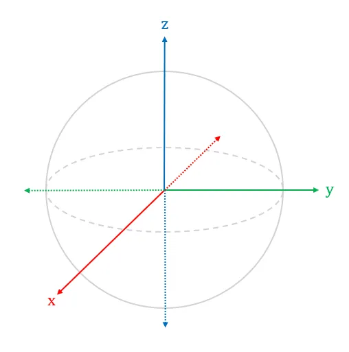
As a result, the quantum state of a qubit can be visually represented as a state vector in a 3-dimension Bloch sphere shown in Diagram 2 above. In case you were wondering, the x-axis represents the real part of the state vector; the y-axis represents the imaginary part of the state vector; the z-axis represents the probabilities of a qubit being observed as 0 or 1 upon measurement.
State Vector for a Coherent Qubit
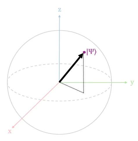
Recall, in Part 1, we briefly mentioned that when a qubit maintains quantum coherence, it possesses a valid quantum state. A valid quantum state is visually represented as a state vector pointing to the surface of the Bloch sphere with a vector length of 1 (also known as a unit vector) as shown in Diagram 3 above.
Conversely, when a qubit experiences quantum decoherence, the invalid quantum state (also known as a mixed state) is visually represented as a state vector pointing within the volume of the Bloch sphere.
Now, let us take a look at how the two basis states are visually represented in the Bloch sphere.
State Vector for Basis States of a Qubit
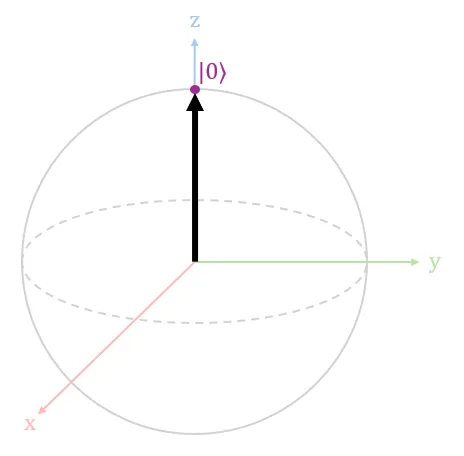
When the qubit |Ψ⟩ is in the |0⟩ state, the state vector points to the surface of the Bloch sphere vertically upwards along the z-axis, as shown in Diagram 4 above. This state vector indicates that there is a 100% chance of observing a 0 upon measuring the qubit.
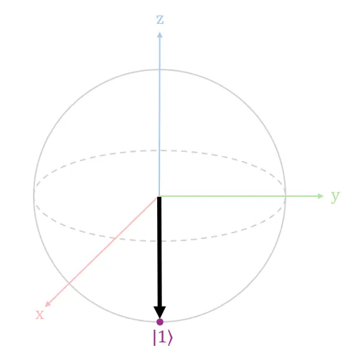
When the qubit |Ψ⟩ is in the |1⟩ state, the state vector points to the surface of the Bloch sphere vertically downwards along the z-axis, as shown in Diagram 5 above. This state vector indicates that there is a 100% chance of observing a 1 upon measuring the qubit.
State Vector for Superposition States of a Qubit
Recall, in Part 1, when a qubit |Ψ⟩ is in a superposition of its basis states, both α and β have non-zero values. Visually, the state vector representing this superposition state can point to any point on the surface of the Bloch sphere except for |0⟩ and |1⟩.
If the state vector points to any point along the equator (the horizontal ellipse with dashes) on the the surface of the Bloch sphere, the qubit will have a 50% chance of observing a 0 or 1 upon measuring the qubit.
Math for Single-qubit Quantum Gate
Recall, in Part 1, that the state of a qubit can be represented as a 2x1 vector. From now on, I will refer to this as the state vector.
A single-qubit quantum gate operation on a quantum state can be represented as a 2x2 matrix multiplying with a state vector. To facilitate visualization of this concept, I will use some quantum gates as examples.
Math for Identity (I) Gate
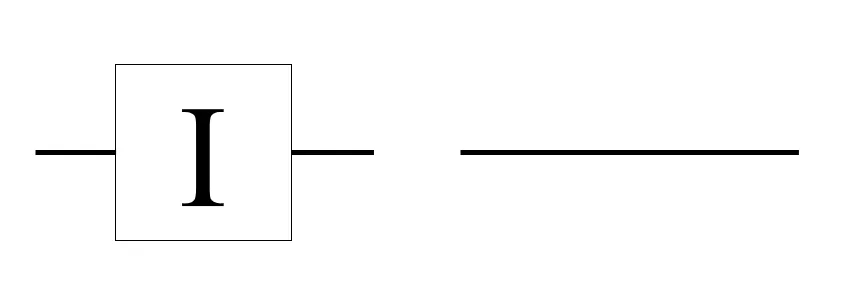
The I gate takes in one qubit input, and outputs the same quantum state without any modifications. The matrix for the I gate is defined as
The effect of the I gate is shown below in both Dirac and vector notations.
Math for Pauli-X (X) Gate
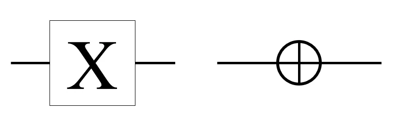
The X gate takes in one qubit input, flips the input from |0⟩ to |1⟩, and vice versa from |1⟩ to |0⟩. Due to this bit-flip operation, the X gate is also commonly known as a "bit-flip operator", "NOT gate" or "addition mod 2". In the Bloch sphere, the X gate performs a rotation on the quantum state vector by π radians around the x-axis.
The matrix for the X gate is defined as
The effect of the X gate is shown below in both Dirac and vector notations.
If you compare the effect of the X gate against the state vector direction in Diagrams 4 and 5, you may have noticed that the X gate actually flips the state vector from up to down, and vice versa. In mathematical terms, the X gate rotates the state vector around the x-axis by π radians.
Math for Hadamard (H) Gate
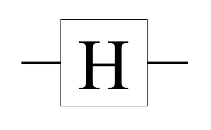
The H gate takes in one qubit input, transforms the input state into a superposition state with 50% chance of observing a 0 or 1 upon measurement.
The matrix for the H gate is defined as
The effect of the H gate is shown below in both Dirac and vector notations.
In the equations above, |+⟩ and |-⟩ are popular labels used to represent commonly used superposition states transformed by the Hadamard gate. We can call |+⟩ the plus state and |-⟩ the minus state.
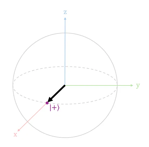
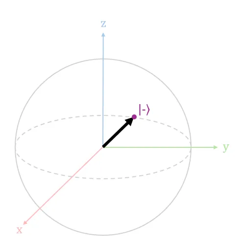
The |+⟩ state is visually represented in Diagram 9 above; the |-⟩ state is visually represented in Diagram 10 above. The state vectors for both |+⟩ and |-⟩ point in opposite directions along the x-axis, but have the same 50% chance to be observed as a 0 or 1 upon measurement. In simpler terms, the state vectors for both |+⟩ and |-⟩ have the same amplitudes in both basis states but different relative phase.
Review
In this article, we learnt how to visually represent the quantum state of a qubit in a Bloch sphere, in particular, for the four quantum states: |0⟩, |1⟩, |+⟩, and |-⟩. We also learnt the mathematical representation for the operations of the I gate, X gate and H gate.
In the next article, I will expand to using the full scope of complex numbers used to represent the quantum state of a qubit and additional quantum gate operations.
Bonus Question
Using our deeper understanding of the H gate, given a quantum circuit with two H gates connected in series along one line, what is the output state of the circuit for the following two input states? (Hint: You can use Quantum-in-a-Browser to check against your answer.)
- Input qubit is in |0⟩ state. In QuICScript, the code is "H,H" for 1 qubit.
- Input qubit is in |1⟩ state. In QuICScript, the code is "X,H,H" for 1 qubit.
See Answer
Using the matrix definition for H gate, we can apply the H gate twice on the input state vector. The resulting effect is two H gate operations will cancel out and return an output state that was the same as the input state. Thus HH|0⟩ = |0⟩, and HH|1⟩ = |1⟩. The math (in both notations) for this is as follows
Author
Nicholas Ho
Nicholas seriously enjoys learning new knowledge. He is so serious about it that his hobby is to collect hobbies. His most enduring hobby, since 1997, is to continuously explore the ever-evolving domains of applied cryptography, software development, and cybersecurity. His latest aspiration is to add the word quantum in front of each of these 3 domains. Nicholas is currently a Senior Cryptographic Engineer at pQCee.com. Akin to many Singaporeans, he also enjoys collecting popular certifications, including a CS degree, an Infocomm Security masters, CISSP, and CISA.